.csv objects
The .csv object file defines a single object using textual information. The object can be used in routes or in trains.
Overview
An object file defines multiple individual polygons (called faces). You can group multiple polygons together using the CreateMeshBuilder command.
Some attributes such as SetColor can be shared among multiple polygons in a group.
The file is a plain text file encoded in any arbitrary encoding, however UTF-8 with a byte order mark is preferred. The parsing model for numbers is Loose, however, Strict output is preferred. The file name is arbitrary, but must have the extension .csv. The file is interpreted on a per-line basis, from top to bottom.
Syntax
Each command resides on a new line. A command contains of a command name, followed by arguments, seperated by commas. Arguments may be omitted by leaving the argument space empty.
CommandName, Argument1, Argument2, Argument3, ..., ArgumentN
Command names are case-insensitive. White space around the name, arguments, and beginning and end of each line is ignored.
Comments can be used anywhere, and must be preceded by a semicolon.
;This is a comment on its on its own line.
AddVertex, 1, 1, 1 ;This is a comment at the end of a line.
All comments are stripped prior to processing.
Commands
The following is a list of available commands.
- CreateMeshBuilder
- AddVertex
- AddFace
- AddFace2
- Cube
- Cylinder
- Translate,TranslateAll
- Scale,ScaleAll
- Rotate,RotateAll
- Shear,ShearAll
- SetColor
- SetEmissiveColor
- SetBlendMode
- LoadTexture
- SetDecalTransparentColor
- SetCoordinates
CreateMeshBuilder
CreateMeshBuilder
This command marks the beginning of a new group of faces. All further commands relate to the CreateMeshBuilder command that was last opened above.
AddVertex
AddVertex, vX, vY, vZ, nX, nY, nZ
- vX
- x-coordinate of vertex in metres. Negative left, positive right.
- vY
- y-coordinate of vertex in metres. Negative down, positive up.
- vZ
- z-coordinate of vertex in metres. Negative backwards, positive forwards.
- nX
- x-coordinate of normal in metres. Optional
- nY
- y-coordinate of normal in metres. Optional
- nZ
- z-coordinate of normal in metres. Optional
- Default values for all fields: 0
Defines a new vertex which can later be used as points of a face/polygon. The order AddVertex commands are important: the first vertex created has the index 0, followed by 1, and so on.
A normal is the direction perpendicular to a face at a point. Changing the normals (combined with the use of a few other faces) can be used to create an illusion of a smooth curved surface. Leaving the normal arguments blank/zero will allow normals to be calculated automatically.
AddFace
AddFace, v1, v2, ..., vMAX
- vI
- Index of vertex to include in the face. Allowed integers: 0 to n-1
- Where n is the number of AddVertex commands in the group above this command
Creates a face around the vertices provided. Specify the vertices in clockwise order when looking at the face. Only convex polygons can be formed.
AddFace2
AddFace2, v1, v2, ..., vMAX
- vI
- Index of vertex to include in the face. Allowed integers: 0 to n-1
- Where n is the number of AddVertex commands in the group above this command
Same as AddFace, except the created face is visible on both sides. The lighting on the backface will be that of the front face.
Cube
Cube, HalfWidth, HalfHeight, HalfDepth
- HalfWidth
- Number indicating half of the width of the cuboid in metres.
- HalfHeight
- Number indicating half of the height of the cuboid in metres.
- HalfDepth
- Number indicating half of the depth of the cuboid in metres.
Creates a cuboid centered around (0,0,0). The cube has 8 vertices and 6 faces.
Tip: move the cube using the Translate and Rotate commands below. This command is equivalent to a series of AddVertex and AddFace commands.
Cylinder
Cylinder, n, UpperRadius, LowerRadius, Height
- n
- Number of faces on the frustrum.
- UpperRadius
- Radius of upper base of frustrum in metres. Negative to omit top cap.
- LowerRadius
- Radius of lower base of frustrum in metres. Negative to omit bottom cap.
- Height
- Height of frustrum in metres. Negative to display inside-out.
Creates a frustrum centered around (0,0,0).
Tip: move the frustrum using the Translate and Rotate commands below. This command is equivalent to a series of AddVertex and AddFace commands.
Translate, TranslateAll
Translate, X, Y, Z , TranslateAll, X, Y, Z
- X
- Translation on the x-axis in metres. Negative left, positive right.
- Y
- Translation on the y-axis in metres. Negative down, positive up.
- Z
- Translation on the z-axis in metres. Negative backwards, positive forwards.
- Default values: 0
Translate moves all vertices (including within Cube and Cylinder commands) above itself in the CreateMeshBuilder group accordingly. TranslateAll moves all vertices above itself in the entire file accordingly.
This command may be called multiple times.
Scale, ScaleAll
Scale, X, Y, Z , ScaleAll, X, Y, Z
- X
- Scale factor on the x-axis.
- Y
- Scale factor on the y-axis.
- Z
- Scale factor on the z-axis.
- Default values: 1
Scale scales all vertices (including within Cube and Cylinder commands) above itself in the CreateMeshBuilder group accordingly. ScaleAll scales all vertices above itself in the entire file accordingly.
This command may be called multiple times.
Rotate,RotateAll
Rotate, X, Y, Z , RotateAll, X, Y, Z
- X
- The x-direction of the axis around which faces will rotate.
- Y
- The y-direction of the axis around which faces will rotate.
- Z
- The z-direction of the axis around which faces will rotate.
- Default values: 0
Rotate rotates all vertices (including within Cube and Cylinder commands) above itself in the CreateMeshBuilder group accordingly. The rotation is done around the origin (0,0,0). RotateAll rotates all vertices above itself in the entire file accordingly.
Example: To rotate an object around the y-axis (rotate around a vertical axis), use x=0, y=1 and z=0.
This command may be called multiple times. Try using in conjunction with Translate(All) functions if needed.
Shear,ShearAll
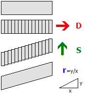
Shear, dX, dY, dZ, sX, sY, sZ, r , ShearAll, dX, dY, dZ, sX, sY, sZ, r
- dX
- The x-coordinate of the vector D.
- dY
- The y-coordinate of the vector D.
- dZ
- The z-coordinate of the vector D.
- sX
- The x-coordinate of the vector S.
- sY
- The y-coordinate of the vector S.
- sZ
- The z-coordinate of the vector S.
- r
- The ratio that indicates how much to displace vectors.
- Default values: 0
Shear performs a shear mapping. Essentially, the object is sliced into planes along the direction D and then displaced along the direction S. r indicates how much to displace vectors - it is calculated by the formula r = y/x.
This command is useful for creating bridges passing over a railway at an angle. This command may be called multiple times.
SetColor
SetColor, R, G, B, A
- dX
- Red value of the colour.
- dY
- Green value of the colour.
- dZ
- Blue value of the colour.
- dZ
- Alpha (opacity) value of the colour (255 is opaque) Optional
- Default values: 255
SetColor applies the colour specified on faces above the command in the current section. If a texture is already used, the texture's colours will be multiplied by the specified colour.
This colour is affected by ambient lighting.
SetEmissiveColor
SetEmissiveColor, R, G, B, A
- dX
- Red value of the colour.
- dY
- Green value of the colour.
- dZ
- Blue value of the colour.
- Default values: 255
SetEmissiveColor applies the colour specified on faces above the command in the current section. Use this command for faces which appear as if it is emitting light.
This colour is affected by ambient lighting - the colour shown on the face is the sum of the specified colour and the ambient lighting.
SetBlendMode
SetBlendMode, BlendMode, GlowHalfDistance, GlowAttenuationMode
- BlendMode
- Blend mode (Normal Default; Additive)
- GlowHalfDistance
- The distance where the glow is at 50% of maximum intensity. 1 to 4095, or 0 to disable attenuation.
- GlowAttenuationMode
- The way the intensity of glow fades out (DivideExponent2; Divide Exponent4)
This command sets the blend mode of face(s) in the current section.
Normal blend mode replaces screen pixels with the texture, while additive will add the colour of the pixels onto the screen, where black will be transparent, while white and bright colours will be seen brighter.
GlowAttenuationMode sets the way the pixels fade off at distance. DivideExponent2 gives a smooth transition which gradually reaches its peak, while DivideExponent4 gives a sharper transition that quickly reaches its peak.
LoadTexture
LoadTexture, DayTexture, NightTexture
- DayTexture
- The texture that will be loaded.
- NightTexture
- The texture that will be loaded when dark. Optional
- Texture paths are relative to the location of the object.
Loads a texture that will be applied to all faces in the current section.
If only a day texture is defined, the object will be shaded depending on lighting conditions on the scene. If a night texture is specified, the day texture will always be at full brightness, and will fade into the night texture based on brightness.
You will almost always need to use SetTextureCoordinates to make the texture fill a face.
SetDecalTransparentColor
SetDecalTransparentColor, Red, Green, Blue
- Red, Green, Blue
- Colour to be used for the colour-key transparency
All the pixels in the texture that are of the exact specified colour will be made transparent.
SetTextureCoordinates
SetTextureCoordinates, VertexIndex, X, Y
- VertexIndex
- The vertex this command refers to.
- X
- The x-coordinate of the texture. Values from 0 (left) to 1(right) (and beyond for repeated textures).
- Y
- The y-coordinate of the texture. Values from 0 (top) to 1(bottom) (and beyond for repeated textures).
This command takes a vertex, and pins the specified point on the texture to the vertex. Textures will repeat infinitely.
Imagine the texture is a flexible, stretchable piece of cloth. Each time this command is used, a thumbtack is pushed through the (X, Y) position of the texture, then the thumbtack is moved to the location of the vertex of the face. You are pinning a point of the picture to each vertex.